
Objectives :
- Analyze the concept of bit time and its relation to the baud rate.
- Analyze the structure of an RS232 frame using the oscilloscope.
- Implement a bidirectional Rs232 communication, using Matlab, across a scheme between two remote Wirid-Lab computers.
Description:
Figure 1 shows the bidirectional communication scheme between nodes A and B. This experiment aims to analyze the physical layer details of the R232 protocol during the communication. For this purpose, nodes C and D are observers or “spies” of the communication. The Oscilloscope (InfinniVision DSO-X 3014T) permits monitoring the signals during the communications process from node 75.
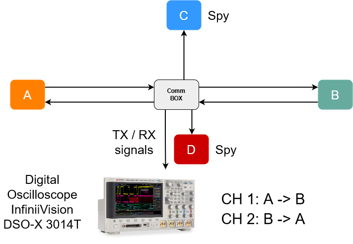
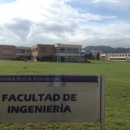
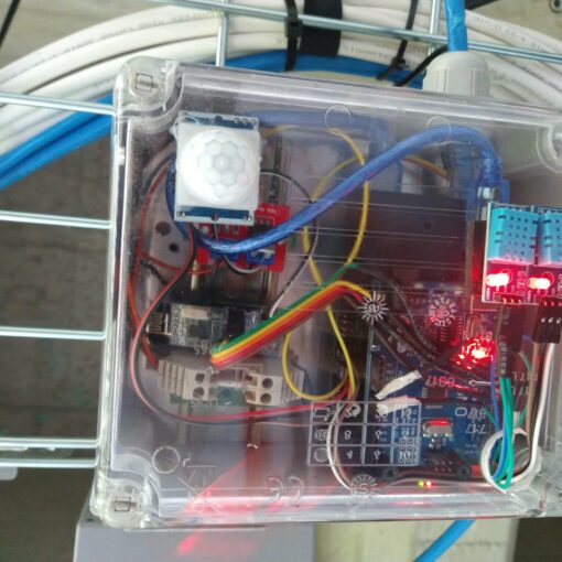
Figure 2 shows the nodes allocation into the laboratory.
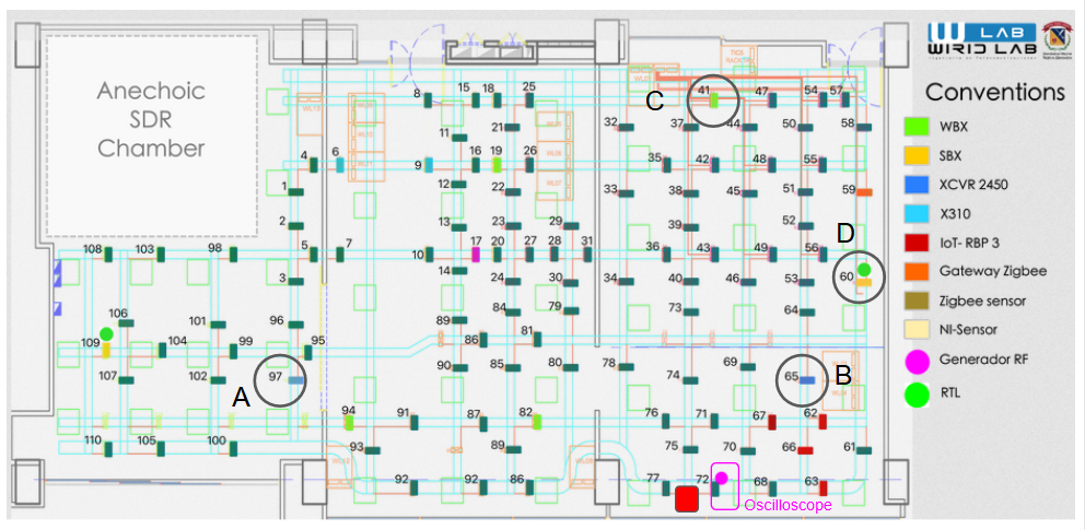
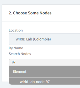
| A | Node 97 |
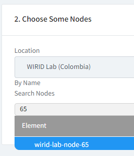
| B | Node 65 |
| C | Node 41 |
| D | Node 60 |
| Digital Oscilloscope | Node 75 |
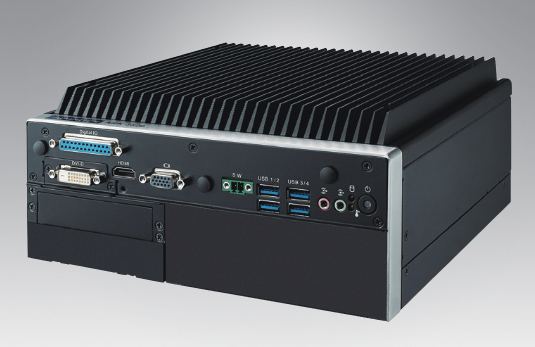
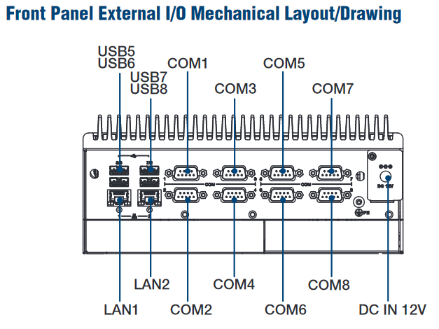
The A, B, C, and D nodes using Advantage (ARK – 3520L) computers. All RS232 connections correspond to COM1.
 |
 |
Procedure
1. Reserve the nodes for the experiment ( 97, 65, 41,60) and the node 75 ( oscilloscope). Check your quota profile. If you can´t reserve all nodes at the same time, ask your professor about the number of students necessary to develop this experiment.
Follow the steps:
A. Set your Timeslot
B. Choose Some Nodes
C. Resume
Choose the Application
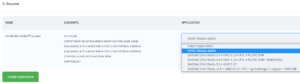
Select: (AMD) Matlab 2020b
Push the button: Create Experiment
2. Execute Matlab for nodes A,B, C and D. Follow the procedure to activate Matlab (https://wirid-lab.github.io/docs/tutorials/matlab)
3. Access the remote oscilloscope following this procedure ( Running the remote Oscilloscope )
4. Check the serial ports for each computer from the command window using the command : >> serialportlist
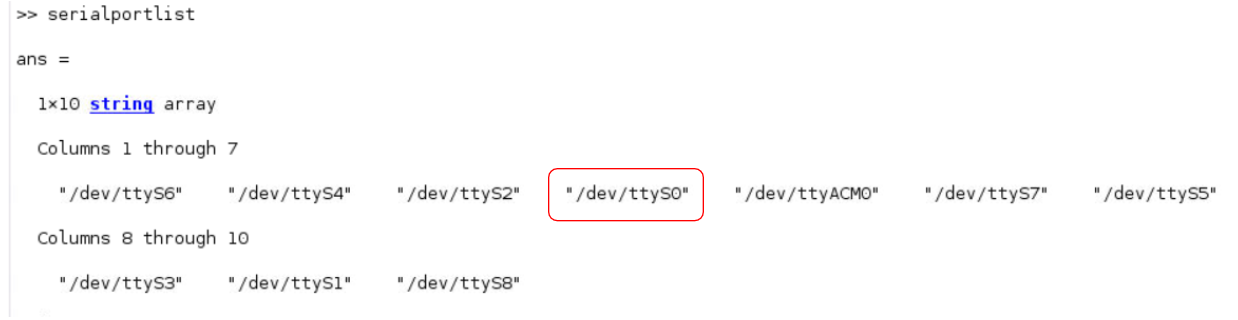
The port name depends on the platform that the serial port is on. In Linux® 64, the COM1 correspond to “/dev/ttyS0”
5. Configure the serial communications parameters for all computers ( https://la.mathworks.com/help/matlab/ref/serialport.html)
Use this comand to configure a basic communication for each computer
>> device = serialport( “/dev/ttyS0”,9600)
From A you can send a message thus:
writeline(device,”UMNG2021″)
From B you can receive the message thus:
>> device
>> data=readline(device)
Now, test the received messages in C and D. In which of the two spies (C or D) receives the message sent from A to B?
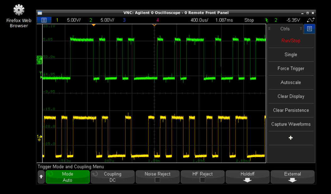
Remember : you can monitor the communication using the oscilloscope at node 75.
To obtain the bits captures in the oscilloscope, remember the configuration of the trigger source, trigger level, and single trigger, Otherwise, you can´t measure the signal.
Recommendations:
- To freeze the signals in the oscilloscope you will need to configure the trigger parameters to single.
- Set the time base according to the bit time or baud rate you are using
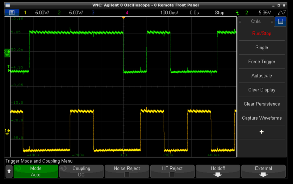
Now you can measure the bit time for each baud rate.
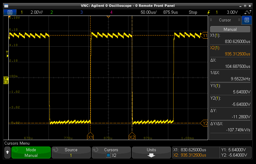
The following videos can help you during the measurement procedure:
2.
3.